Introduction
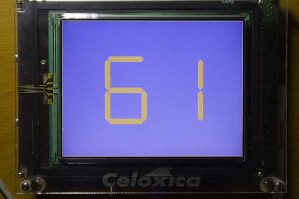
This laboratory introduces you to the touchscreen/video panel on the RC200E. The project is to draw the ASCII codes for characters typed on the keyboard as graphical seven-segment displays on the screen. The following image gives an idea of what your output might look like after typing the character 'a'. Your colors may vary, and the lozenge shape for the individual segments is optional: simple rectangles will suffice!
There are several ways of generating video images on the screen, but this lab investigates just one of them. And it’s a technique that will require you to design code that will be radically different from a software solution to the problem.
Procedure
-
Configure a new project for both Debug and EDIF design flows.
Start DK, and re-open the workspace you created in Laboratory I. Create a new project in that workspace named Keybd2Video. Be sure you select Xilinx Virtex II Chip as the project type.
Delete all the configurations for this project except Debug and EDIF.
Set the Debug Configuration options.
Use the same settings, including libraries, as you used for Laboratory II
-
Write a first version of the program and simulate it.
Use the program from Laboratory 2 as a model, and look up the documentation on PalVideoOut in the PAL Reference Manual. The macros you will need are PalVideoOutGetX(), PalVideoOutGetY(), and PalVideoOutWrite(). You will also need to initialize the VideoOut system in the usual way:
par { PalVideoOutRun(PalVideoOutOptimalCT(ClockRate), ClockRate); seq { PalVideoOutEnable(PalVideoOutOptimalCT(ClockRate)); while (1) { PalVideoOutWrite(PalVideoOutOptimalCT(ClockRate), pixel); } } }Notes
(1) The PAL Reference Manual erroneously omits the second argument to PalVideoOutRun. (2) You can save some typing by defining a macro expr for PalVideOutOptimalCT(ClockRate).
The structure of the program should be as follows: Have one endless loop read from the keyboard. Each time it gets a character, no matter what character it is, toggle the value of a global variable between two contrasting RGB color values. A second endless loop simply writes the value of this color value to the screen on every clock cycle.
For this code to work, your program must use a clock rate that matches the video clock of the touchscreen display: 25.175 MHz. The effect should be that the entire display changes color each time you type a character.
Note that the PAL Virtual Platform changes when you add video output to the design. Instead of the panel for keyboard input, there is now a tab for a second panel that shows the video output, and this panel is where you now type in the simulated keyboard characters. (Look where it says, “Keyboard Input”.) And there’s good news! No more scan codes; just type characters on the PC keyboard. Observe the speed with which the simulated screen is updated during simulation. You can see the progress of the refresh cycle in the status bar at the bottom of the Virtual Platform window. If you move your mouse over the video panel, the coordinates of the mouse and the color at that position are also shown in the status bar.
-
Test the first version of the program on the RC200.
The visual effect should be the same as for the simulated version, but it should take just 1/60 sec to do a complete screen update.
-
Draw a pattern based on the coordinates of each pixel.
The PalVideoOutGetX() and PalVideoOutGetY() macro expressions will give you the current position in the touchscreen display’s refresh cycle. You can use the coordinate information to select what color to draw at that position provided you execute the PalVideoOutWrite() operation in the same clock cycle. Alter your existing program (do not create a new project) so it draws a one-pixel wide border around the touchscreen using one of your two favorite colors; fill the remainder of the screen with your other favorite color. You can use PAL macros, PalVideoOutGetVisibleX() and PalVideoOutGetVisibleY()to get the dimensions of the touchscreen (good for making your code portable to other LCD displays), or you can use the known dimensions for the RC200E: 640x480. Typing a key should switch the fill and border colors with each other.
Simulate your code and verify that the border is exactly one pixel wide and that it is at the outside edges of the screen. Note there is a problem with the virtual platform: if you make it big enough so you don’t have to scroll to see the entire display, there is no way to see the right and bottom edges. So you have to keep the size small enough to force the scrollbars to appear.
Once the simulation is right, test it on the real device.
-
Draw two seven segment displays on the screen.
If the current position in the refresh cycle is inside one of 14 rectangles, write the foreground color. Otherwise, draw the background color. Test both by simulation and on an RC200.
-
Draw the hexadecimal representation of the ASCII code of the most recently typed charager using the seven segment displays on the touchscreen